The MKJ Plant
The MkIII Plant
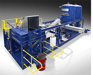
The Plant in the photo is specifically designed for the treatment of a wide variety of oily waste classifications from fresh slop oils stored in tanks to mixtures of weathered oily waste held in pits, lagoons and lakes. Its capacity is determined mainly by the viscosity of the feed. For example waste oils with a viscosity in the range of Cst30 at 50°C can be treated at 10 m3/hr whereas those having a Cst600 at 50°C can be treated at 2 m3/hr. We therefore recommend treating at a temperature of 95°C to maximize the plant capacity and to improve the overall separation performance thereby producing the highest quality oil. A major variable in treating slops are the concentrations of common contaminates, water & solids. This plant can handle solids up to 40% in the feed and any combined ratio of oil & water. This plant comes with a variety of options to choose from that include: plant heat (hot water boiler or steam converter), buffer tanks for receiving oily waste and tanks for clean oil and clean water. Other important features are also included or quoted as options to the MKIII. This include heat exchangers, treating chemical dosing systems, sludge solids thickeners, pit excavation assemblies, cabins for storage of tools and spare parts, site laboratory, site office and site sanitation. The primary supply included with the G-force MKIII Plant is an 8-g elliptical screen separator where coarse particles and floating debris are separated before feed to the primary separation equipment. G-force applies 3000-g 2-phase decanters to handle any load of solids normally associated with oily waste. This plant is designed to handle solid contaminates from any range up to 40% in the feed without affecting performance. The job assigned to the 2-phase decanter is to remove the majority of solids from the screened effluent. Following the 2-phase decanter the G-force system is designed to raise the decanter effluent temperature to >95°C, apply the proper mix of treating chemicals at our RTR500 residence time reactor (to insure minimization yet performance optimization of treating chemicals) and then to feed directly into the 6000-g 3-phase centrifuges to separate the water and any remaining sediments from the oil phase for the purpose of achieving the highest quality treated oil in the smallest operational footprint. The 3-phase 6000-g vertical disc-stack centrifuge used by G-force is unique for the treatment of difficult to separate oily waste. This is especially evident when compared to 3-phase horizontal 3000-g range scroll decanters, in that 3-phase decanters are more sensitive to changes in oil and water feed ratios typical of oily waste thereby resulting in off-spec oil and water. Typically 3-phase decanters, with their low g-force (3000-g compared to 6,000-g) require pre-treatment in special residence tanks for batch feed preparation all of which consumes time and personnel. The G-force system eliminates the requirement of batch blending residence tanks and as a result produces a consistent higher quality treated oil phase. The MKIII plants are designed to the new EU ATEX electrical specifications and/or Class I Div 2 zoning for compliance involving Oilfield operations. A special design feature of the MKIII is the interconnecting pipe & pump works (what we call the logic box) where all plant components centrally flange thereby minimizing space requirements, making installation and commissioning a quick, simple and easy task and providing excellent operations logic and safety monitoring as required for the treatment of the various classifications of oily waste. This allows the plant operator total flexibility when routing and treating the various oily waste streams. G-force is the only company providing this operational freedom through its logic flow design box.
Principle of Operations
The feedstock is picked up by the MKIII plant-installed pumps (either from the clients tanks or open dump site) for feeding into the plant process. Process heat is provided by G-force through our provision of a Hot Water Boiler, or clients steam via our Site Steam Converter (clients choice of options) and by way of the MKIII installed Heat Exchangers whereby hot water is utilized to heat the oily waste to the required range of 95°C by the time it is fed to the 6000-g 3-phase Oil Purifying Centrifuge. To begin the process the waste oil feed is first pumped across the screen separator and then into the 2-phase decanter. The primary application of the decanter is to remove 97% to 99 % of the solids. After the solids are removed the decanted effluent is ready for treatment in the 6000-g 3-phase centrifuge. Depending on the contamination volume of water contained in the oil phase, the oil-water droplet sizes and the volume of particle sizes in the range of 5 mµ to 10 mµ determines if Treating Chemicals are required in the separation process. Normally at 6000-g treatment of oily waste can be accomplished without the use of Treating Chemicals thereby significantly reducing cost. However in most cases treating chemicals are required to improve the capacity flow and separation performance of the plant. Therefore the MKIII is delivered with a static mixer where treating chemicals are first injected to mix with the contaminated oil. Immediately following the static mixer the feed enters the G-force RTR Dynamic Residence Blender to insure the treating chemicals come into direct contact with the water phase droplets and the sediment particles so as to de-emulsify or coalesce them for separation. The treated oily waste leave the RTR Blender and immediately enter the 6000-g High Speed 3-phase Centrifuges to separate the oil &water, along with the remaining sediments. The separated oil is immediately transfer to the clean oil export tank and ready to be returned to the client or sold into the market place. The separated water directly dispatched from the 6000-g centrifuge contains oil-in-water in a range of 500 ppm to 2% oil. In many cases this water specification is acceptable for delivery or pumping to the client’s wastewater treatment facility (WWTF). Most refineries for example have their own WWTF systems. However if required, G-force as provided with the MKIII plant shown in this photo, will include its 12,000-g Water Concentration Centrifuge (WCC) to treat the water separated from the 6,000-g 3-phase Oil Purifying Centrifuge so that it meets the disposal regulation for land or sea. Water is normally dispatched from the 12,000-g WCC in the range of 5 ppm to 10 ppm oil-in-water. Solids separated from the 3-phase centrifuges represent a minor portion of the solids as the majority of solids are separated up-stream at the screen separator and decanter. These minor portions of solids discharged from the 6000-g centrifuge are pumped into a G-force designed sludge thickener. The solids removed from the 3-phase centrifuges are dispatched through side ports by means of a self cleaning mechanism using a water operated hydraulic bowl where a small ~10 liter water cushion leaves with the solids during each ejections interval. Solids are ejected from the bowl approximately each 10 minutes and this time interval is set according to the solids content in the feed to the centrifuge. The ejected solids, along with the water cushion, are deposited into a solids conveyor and transferred into the Sludge Thickener where the solids are thickened (dried) and conveyed into a waste skip for final disposal and the free water is collected and returned to the process. Finally the total of solids separated from the screen separator, the decanter and the centrifuges are directly conveyed into waste skips for final disposal and declassification. Where clients are interested G-force accepts to provide the declassification of oily solids. This is an important option of our services. Finally the MKIII Plant as shown in the photos represents one of several plant designs standard to our product line. If required G-force specializes in the design and manufacture of custom plants to meet any defined capacities specific to the needs of our customers. This is achieved by the simple addition of multiples of the main components to either achieve a greater capacity or performance specification.
Installation & Serviceability
G-force plants are supplied with one-year of spares and come with a recommended maintenance schedule based on each 2000 hours of operations (4 times per year). All primary equipment is supplied as a complete package including special tools and is ready for installation on a level concrete pad. Further to our service a team of G-force engineers supervise the plant installation and commissioning on site, which normally takes ~14-days. The client is expected to provide a level plant installation concrete pad (all civil data are supplied by G-force), a 15 ton forklift to unstuff the shipping containers, and a 50 ton crane to lift and place all the plant module into place on the concrete pad. Installation tools and special equipment servicing tools are also provided with the delivery of the plant. Immediately following plant commissioning the actual operations are ready to commence. No other requirements for installation are needed except for the client to bring service points (electricity, water, waste feed and clean oil-water take off pipes) to the concrete pad for hook up purposes. G-force provides all utility details and placement. If required G-force also supplies all climate buildings dimensionally specific for the plant footprint as delivered. Following plant-commissioning G-force will provide on site training to the clients assigned Plant Operator to insure a smooth handover. This is done by arranging training contracts with clients whereby our operations engineer remains at the clients site for as long as necessary to train the local staff up to operational competence and full take-over. In our experience we have commissioned plants where the clients engineers took over immediately after commissioning, this we consider exceptional. Normally training requires an additional 30 to 90 days period after commissioning for the local engineers to reach operational competency.
Dimensions & Utilities
Basically, if the client orders a plant with a heat supply from G-force, the only utility requirements is electrical power, diesel for the Hot Water Boiler and plant operations water. If the client has a steam heat supply only electricity and water are needed. The kW and water depend on plant size and options chosen, details of which are provided with our full quotations. For the MKIII plant shown in the photo the electrical requirement is 120 kW of installed power and the footprint is ~L20m x ~W15m (includes walkways).
Delivery timeframe, plant certification & equipment warrantees
Delivery, from the time of approved order placement up to ex-works, requires G-force 12 weeks to construct the plant shown in the photos. BUT delivery is mainly dependent upon the delivery timeframe of the major components. Therefore in most circumstances we advise clients to plan for a delivery period of 22 to 26 weeks up to our Ex-works. It is the policy of G-force that before shipment the plant is fully assembled at the factory so that it undergoes a complete Factory Mechanical Completion Certification. The buyer is asked to attend this certification. During the last 14-day period of plant fabrication G-force invites two of the Buyers assigned engineers to our manufacturing facility in Holland for schooling and hands on training at our cost. G-force provides the Buyer a Mechanical Warranty to certify that the plant delivered is under warranty for 100% of the supply against any defects for the first year of operations, starting from the date of commissioning, or for a period of 18 months from the date of ex-works delivery, whichever comes first. We have experiences with delivery and installation all over the world.